
The Connection Between Hydraulic Circuit Design and Fluid Transfer Systems
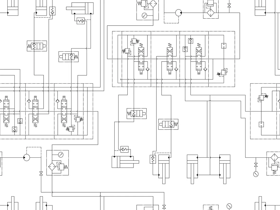
Hydraulic circuit design and fluid transfer system design are intertwined for contract manufacturers and OEMs relying on their service. Circuits define what the system does with hydraulic power, while the fluid transfer system provides a physical path that delivers that power safely.
RB Royal highlights the relationship between these two designs and how one impacts the other.
Two Parts of One System: Hydraulic Circuit and Fluid Transfers
Hydraulic circuits traditionally include a pump, reservoir, valves, actuators, and conductors. The role of a hydraulic circuit is to direct pressurized fluid so a cylinder or motor produces the intended force, speed, direction, and sequence of motion. This works as part of a fluid transfer system overall.
| Hydraulic Circuit Design | Fluid Transfer System Design |
|---|---|
| Establishes the functional logic of the machine | Establishes the physical means of moving fluid between components |
| Selects and arranges pumps, actuators, valves, accumulators, filters, and controls | Selects tubing, hose, pipe, manifolds, fittings, couplings, clamps, reservoir connections, and routing |
| Defines pressure levels, flow paths, motion sequences, load holding, speed control, and safety functions | Determines actual flow velocity, pressure drop, heat rejection, contamination control, vibration behavior, accessibility, and leak risk |
| Usually begins as a schematic using standardized symbols | Becomes a layout, plumbing plan, BOM, and installation specs. |
Circuit Designs that Impact Fluid Transfer
There are numerous circuit design choices that have an immediate impact and change on fluid transfer requirements.
| Circuit Decision | Fluid-Transfer Implication |
|---|---|
| Higher system pressure | Requires adequately rated tubing, hoses, fittings, seals, manifolds, and safety margins |
| Larger pump flow | Requires larger flow passages or lower allowable velocity to limit pressure loss and heat |
| Multiple actuators operating together | May require shared supply lines, branch sizing, priority flow control, or manifolds sized for simultaneous demand |
| Load sensing or pressure compensated pump | Requires correctly routed load sense lines, low leakage connections, and attention to pilot orifice contamination |
| Hydraulic motor use | Needs properly sized supply, return, and case drain lines |
| Cylinder load holding | Needs short, protected lines between counterbalance load holding valves, and the actuator to prevent loss of control |
| Proportional or servo control | Requires clean fluid, stable pressure, low noise plumbing, and carefully managed pressure drops |
| High duty cycle operation | Needs heat balance analysis, reservoir capacity, cooling, and return line conditions |
| Mobile equipment installation | Requires flexible hose routing, bend radius control, abrasion protection, clamp design, and articulation allowance |
Where Fluid Transfer Systems Impact Reliability
There are key design considerations to include for engineering teams of contract manufacturers and OEMs before manufacturing takes place.
Contamination control where filtration is properly located within the hydraulic circuit design that protects sensitive proportional components and use clean assembly practices. Heat management is another item to consider since every pressure drop becomes heat within the system.
Identifying items that support mechanical durability for systems matters greatly for both hydraulic circuit design and the entire fluid transfer system. Tubes are the preferred path for fixed, high-pressure routing since they are compact and durable. Hoses should be considered where motion, vibration isolation, and installation flexibility is required.
Improve and Enhance Your Hydraulic Circuit Design by Partnering with RB Royal
Since 1942, RB Royal has served as one of the United States’ leading turnkey tube manufacturers for hoses, hardlines, and hybrid custom fluid transfer solutions. In our Fond du Lac, Wisconsin facility, we design, engineer, manufacture, and validate all of the necessary components for your fluid transfer system.
We can directly support hydraulic circuit design with our Design-ufacturing program. This program puts our full design capabilities to the test by finding ways to make your drawings a reality.
All of our manufacturing, design, and engineering operations are backed by our robust quality management systems, which have been continuously ISO 9001 certified since 1999. We document and verify all ECRs, conduct internal testing/verification, and maintain a system of third-party verification of all fixtures. Our fully equipped on-site testing lab is equipped to check virtually every detail from dimensions to cleanliness testing. In addition to offering full PPAP and FAI, we also can coordinate off-site, third-party testing, and verification as required.
Contact RB Royal today and let’s work together to iron out your hydraulic circuit design.